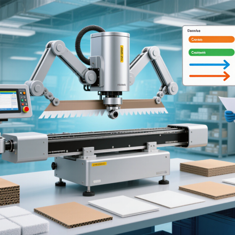
| Cutting Principle | Computer-controlled oscillating knife | A small blade moves rapidly up and down while the tool head follows vector paths generated from CAD or structural-design files. | Produces clean cuts without the heat-affected edge associated with laser cutting. | Suitable for corrugated board, folding-carton board, honeycomb board, foam board, and other sheet materials within the machine’s rated thickness. |
| Common Working Area | Approximately 1,200 × 900 mm to 1,600 × 1,200 mm | The usable bed area determines the maximum sheet size that can be processed in one operation. | Larger beds reduce sheet trimming and make it easier to proof medium- and large-format carton layouts. | Choose a bed that is at least slightly larger than the largest blank or nested layout to be tested. |
| Compatible Board Thickness | Typically about 0.5–15 mm, depending on material, blade, and tool configuration | Different blade geometries and cutting depths are selected for paperboard, single-wall corrugated board, double-wall corrugated board, and layered materials. | Allows structural prototypes to be tested using materials close to production stock. | Confirm the actual thickness range for E-flute, B-flute, C-flute, laminated board, and any specialty substrate used in production. |
| Cutting Accuracy | Commonly specified around ±0.1–0.3 mm under controlled conditions | Servo motors, linear guides, calibrated tool offsets, and software compensation control the position of the knife. | Supports accurate fit checks for panels, locking tabs, slots, windows, and folding scores. | Ask for a test cut on the intended board grade; material compression and sheet flatness affect real-world accuracy. |
| Maximum Tool Speed | Often approximately 600–1,200 mm/s; practical speed varies by material and geometry | The controller adjusts velocity during straight cuts, tight corners, small features, and direction changes. | Shortens proofing cycles while maintaining control around detailed carton structures. | Do not compare speed alone; corner quality, acceleration, tool changes, and total job time are more meaningful. |
| Oscillating Knife Frequency | Commonly up to approximately 10,000–20,000 strokes per minute, depending on the tool system | Rapid vertical blade motion separates fibers and reduces the need for the material to be dragged through the cut. | Improves cutting performance on corrugated board and other fibrous sheet materials. | Higher frequency is not automatically better; blade type, amplitude, material density, and feed speed must be matched. |
| Scoring and Creasing | Tool-based scoring with interchangeable wheels or creasing blades | The machine scores fold lines at controlled pressure instead of removing material along the fold. | Enables folding and assembly checks before a die or mass-production tooling is made. | Use a dedicated scoring tool for clean folds and verify that the score direction matches the board’s grain and structure. |
| Registration Method | Vacuum hold-down plus printed-mark, camera, or origin-based registration | Vacuum stabilizes the sheet while sensors or a vision system locate reference marks and compensate for print-to-cut deviation. | Useful for printed cartons, windows, graphics, and cutouts that must align with artwork. | A camera system is preferable when printed registration tolerance is important or sheets may shift during loading. |
| Vacuum Hold-Down | Variable vacuum zones or full-bed vacuum; capacity depends on pump and table design | Airflow pulls the board against the cutting surface to limit movement during knife oscillation. | Reduces sheet displacement, lifting, and dimensional variation during cutting. | Check whether the table has zoned control and whether porous corrugated board requires additional sealing or masking. |
| File Compatibility | Common vector formats include DXF, AI, PDF, EPS, and SVG; exact support depends on software | Design software converts vector paths into cutting, scoring, perforating, and marking instructions. | Connects structural packaging design with rapid physical prototyping. | Confirm support for layers, tool assignments, scale units, line colors, overcut settings, and duplicate-path detection. |
| Typical Proofing Workflow | Design → preflight → material setup → registration → cutting and scoring → folding → inspection | The digital file drives separate tool operations in a defined sequence, usually with scoring completed before or together with cutting. | Creates a repeatable method for checking dimensions, assembly, appearance, and protection. | Standardize file naming, material codes, tool settings, and inspection checkpoints for reliable sample approval. |
| Prototype Turnaround | Often minutes to a few hours for a small batch, excluding design and finishing time | No physical die is required; the machine cuts directly from the approved digital layout. | Accelerates design revisions and reduces waiting time during carton development. | Actual time depends on sheet loading, tool changes, number of samples, cutting complexity, and operator preparation. |
| Tool Change Capability | Manual or automatic switching among knife, creasing, perforation, and marking tools | Different tool heads perform separate operations on the same sheet. | Supports complete carton prototypes without transferring the sheet between multiple machines. | Automatic tool recognition and preset offsets can improve repeatability for frequent prototype work. |
| Edge Quality | Clean, cold-cut edge with possible fiber fraying on unsuitable materials or settings | The blade mechanically separates the sheet instead of vaporizing or melting it. | Preserves the natural appearance of paper-based packaging and avoids laser discoloration. | Use sharp, material-appropriate blades and optimize speed, oscillation, pressure, and overcut settings. |
| Production Suitability | Best for sampling, short runs, design validation, and customized packaging | Digital cutting eliminates the need for a dedicated cutting die for every new design. | Reduces tooling cost and is efficient when product variants or order quantities change frequently. | For high-volume repetitive production, compare total cost and throughput with rotary or flatbed die cutting. |
| Main Advantages | Fast design iteration, low setup cost, flexible materials, and no heated cutting edge | Digital data controls the tool path, so a revised carton can usually be processed without manufacturing a new die. | Well suited to packaging development, promotional packs, limited editions, and structural testing. | Prioritize software workflow, serviceability, calibration, and sample quality rather than headline speed alone. |
| Main Limitations | Lower throughput than dedicated die-cutting equipment for very large repetitive orders | Each sheet is processed by a programmable tool path rather than by a single high-speed die stroke. | Provides flexibility, but may not be the lowest-cost method for standardized mass production. | Evaluate expected monthly volume, average job size, labor, maintenance, and material waste before purchase. |
| Best-Fit Buyer Profile | Packaging designers, converters, sample rooms, short-run manufacturers, and R&D teams | Digital tool paths make frequent design changes and multiple carton styles practical. | Improves speed from concept approval to a foldable, reviewable physical sample. | Choose a system with appropriate bed size, reliable scoring, vision registration, and accessible technical support. |


 Your message must be between 20-3,000 characters!